At this point in time, the core software emulation is functioning as expected which leaves only fine tuning to be completed. The only firmware changes I am making at this point are to add new features as people suggest them. One of which is to to be able to zero the tilt bob between players (ie tournaments).
Phase 7: Installation
Have you ever designed a product only to say, "Ooops, I didn't think of that at the time"? Well, this happens to be one of those times. Two things jumped out at me the second I tried to install the PCB.

The first thing that needs to be done once the Electronic Tilt is installed, is to fine tune the levelling of the device. This is really no different than ensuring a mechanical tilt plumb bob is centered within the bracket however, instead of a physical adjustment, we do an electronic one.

By clicking on the green buttons, we can bring the values of the X and Y axis as close to zero as possible in real time. We can also adjust the Z axis to bring as close to +/- 1.0000 as possible.
The values are immediately saved in non-volatile memory allowing them to be loaded the next time the machine powers up. In addition to saving the values in non-volatile memory, I've also included the option to backup/restore the offsets to the internal file system.
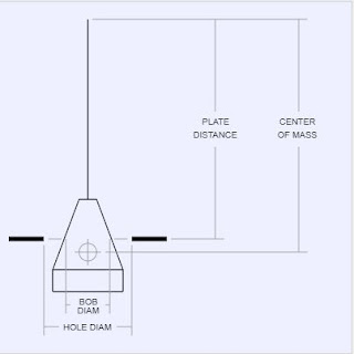
Accurately simulating the movement of a mechanical tilt bob requires us to first understand the characteristics of its movement. Newton's Laws of Motion cover the majority of this topic and since they are basic scientific principles, I'll spare you the details. These are controlled by the following user settable variables: BOB DIAMETER, PLATE DISTANCE, HOLE DIAMETER and CENTER OF MASS.
The remaining characteristics of movement involve friction. The video link (~3:05) shows what we need to accomplish.
https://youtu.be/E4ZZT2nvgkg?t=182
In the video, the fore/aft movement came to a rest after about 7 cycles while the right/left movement took around 42. With that in mind, let me introduce you to X DECAY and Y DECAY. These parameters affect the settling time of the tilt bob. I'm using a bit of reverse logic in my calculations so a value of 1.000000 is no decay/friction while a value of 0 represents full friction. I've allowed 6 digits of precision in these variables, so really fine tuning is possible.
Numerous decay values were tested in order to achieve the 7/42 swings of the tilt and my visual representation of the tilt plumb bob was an excellent means of observing this. From these tests, I came up with a starting value of 0.999 for the X axis and 0.996 for the Y axis. I like to point out that my eyes sometimes confused the sixes and nines so I ended up using 0.999001 and 0.995999 respectively ... not only did this prevent my misreading of the values, but it also served as a reminder that I have 6 digits of precision instead of 3.
EDIT: It was difficult trying to bump the table consistently after making minor changes to the decay values. Sometimes I hit harder than I did previously and so my results were inconsistent. The latest firmware revision now has test buttons to start the tilt at its maximum.

Phase 12: Do the Shake
Somebody was asking me for video of the Electronic Tilt in action. Here's a short clip of what happens when you shake the machine.
I'm happy to say that the device has performed as expected. The individual tuning parameters (ie DECAY, DIAMETER, etc.) could be played with a little more to help zero in on the "ideal" settings, but that brings up to the question of 'What are the ideal settings?' This is where I'd like to see one of of my devices in the hands of the players ... both real and virtual pinball players since there is an application in both markets. That way, a consensus can be made on standard settings for home and tournament use.
To be continued ...
Phase 7: Installation
Have you ever designed a product only to say, "Ooops, I didn't think of that at the time"? Well, this happens to be one of those times. Two things jumped out at me the second I tried to install the PCB.
- The board is just slightly too large
- No holes for mounting

The whole idea of making this project was to replace a mechanical tilt bob with minimal changes to an existing pinball machine. Ideally, the PCB should have fit between the top and bottom metal piece of the existing tilt bob ... in other words, no changes to the existing setup and the ability to quickly switch back if required. My measurements were close, but not close enough. The board was about 3~5 mm too big to fit within the space. Unfortunately, this required the removal of one half of the tilt bob bracket which can be seen by the holes between the board and the ball and under the tie-wrap.
The other issue I ran into was I didn't think about mounting holes. In the back of my mind I was thinking velcro would work, but I'm sure the board would come loose over time. Luckily there were a couple of spaces on the PCB I could drill into.
Phase 8: Connecting to the Existing Tilt Mechanism and Power

The two white wires connect to the existing tilt brackets using spade connectors. Again, the whole idea was to quickly and easily tap into the existing wiring without any major modifications to the machine.
Power connects on the top left
Phase 8: Connecting to the Existing Tilt Mechanism and Power

The two white wires connect to the existing tilt brackets using spade connectors. Again, the whole idea was to quickly and easily tap into the existing wiring without any major modifications to the machine.
Power connects on the top left
Phase 9: Staying on the Level
The first thing that needs to be done once the Electronic Tilt is installed, is to fine tune the levelling of the device. This is really no different than ensuring a mechanical tilt plumb bob is centered within the bracket however, instead of a physical adjustment, we do an electronic one.

By clicking on the green buttons, we can bring the values of the X and Y axis as close to zero as possible in real time. We can also adjust the Z axis to bring as close to +/- 1.0000 as possible.
The values are immediately saved in non-volatile memory allowing them to be loaded the next time the machine powers up. In addition to saving the values in non-volatile memory, I've also included the option to backup/restore the offsets to the internal file system.
Phase 10: To Tilt Or Not To Tilt. That Is The Question.
A mechanical tilt bob is electrically equivalent to a switch which opens and closes so an electronic version should act in a similar fashion. I could have used an electro-mechanical relay which physically opens and closes, but anything mechanical is subject to wear. Instead, I chose to do this electronically. As such, my first test was to verify I could trigger the tilt in the machine. Instead of shaking the machine to cause a tilt, I included a test button to manually trigger the tilt ... much easier.
In order to understand how a pinball machine detects a tilt condition, I need to introduce you to the TILT HOLD setting. In other words, how long is the tilt switch closed for. Every pinball machine has a switch matrix which scans (polls) through rows and columns to check the state of the switches attached to it. This happens continuously but requires a certain amount of time in order to read the state correctly. Based on my research, 10 ms was a good starting point ... and based on my initial testing, this number appears to be correct. I could set it to a higher number (seconds vs milliseconds), but this could have the potential to cause issues with tilt warnings being detected multiple times as the switch polling period repeated.
Phase 11: Zen and the Art of Tuning an eTiltAccurately simulating the movement of a mechanical tilt bob requires us to first understand the characteristics of its movement. Newton's Laws of Motion cover the majority of this topic and since they are basic scientific principles, I'll spare you the details. These are controlled by the following user settable variables: BOB DIAMETER, PLATE DISTANCE, HOLE DIAMETER and CENTER OF MASS.

The remaining characteristics of movement involve friction. The video link (~3:05) shows what we need to accomplish.
https://youtu.be/E4ZZT2nvgkg?t=182
In the video, the fore/aft movement came to a rest after about 7 cycles while the right/left movement took around 42. With that in mind, let me introduce you to X DECAY and Y DECAY. These parameters affect the settling time of the tilt bob. I'm using a bit of reverse logic in my calculations so a value of 1.000000 is no decay/friction while a value of 0 represents full friction. I've allowed 6 digits of precision in these variables, so really fine tuning is possible.
Numerous decay values were tested in order to achieve the 7/42 swings of the tilt and my visual representation of the tilt plumb bob was an excellent means of observing this. From these tests, I came up with a starting value of 0.999 for the X axis and 0.996 for the Y axis. I like to point out that my eyes sometimes confused the sixes and nines so I ended up using 0.999001 and 0.995999 respectively ... not only did this prevent my misreading of the values, but it also served as a reminder that I have 6 digits of precision instead of 3.
EDIT: It was difficult trying to bump the table consistently after making minor changes to the decay values. Sometimes I hit harder than I did previously and so my results were inconsistent. The latest firmware revision now has test buttons to start the tilt at its maximum.

Phase 12: Do the Shake
Somebody was asking me for video of the Electronic Tilt in action. Here's a short clip of what happens when you shake the machine.
To be continued ...


